Chapter 17: Array


The Array module used to manipulate mathematically one, two, or a series of
block, sisim, contour, or surface 2D or 3D grid files (For valid file formats, refer to
Chapters 11 and 13). Depending on the options selected, operations include addition,
subtraction, multiplication, division, averaging, minimum, maximum, probability value
within a range, reclassification, and basic statistics. These are basic grid tools used in
Geographical Information Systems (GIS). This tool can be useful for data preparation,
or for data and result analysis. For example, by reclassifying a contaminant plume map
to a cost of remediation map, estimates can be made about site clean up costs.
The array application is composed of two sections (Figure 17.1); the main menu-
bar, and the text status area. The menu-bar is used to select all array commands and
the text area contains relevant data about the status of the program or the state of on-
going calculations.
- NOTE: Within this chapter, any time an array is refered to, a 2D an or 3D grid is
implied. This program does not perform matrix algebra.
NOTE: For correct results on operations with two or more grids, all the grids must
have exactly the same grid dimensions (i.e. the number of columns, rows and
layers must be the same).
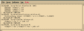 Figure 17.1
Menu Items
Examples
Command Line Arguments
File Formats
Mathematics
The Main Menu:
The main menu controls nearly all the program operations; files can be opened
and saved, calculations can be made, and help can be requested. For array there are
five items on the main menu:
File,
Array,
Log, and
Help
(Figure 17.1). File
controls file handling (opening, saving, viewing, and naming files), and allows the user
to quit the application. Method specifies what gridding algorithm will be used. Array
allows the user to specify a series of mathematical operations that can be performed on
one, two, or a series of 2D or 3D grids. These options are currently disabled. Log allows the user to save and view anything
which has been written by the program or the user in the status text window. Help
gives the user a selection of pop-up help topics. Each menu item is fully described
below with all the available options.
[TOP] [SYNTAX]
File:
The File sub-menu options control file and print handling, and exiting the
program. The options include Save Preferences and Quit.
Save Preferences:
When using programs with many user options, it is not possible for the program
to always pick reasonable default values for each parameter or input variable. For this
reason preference files were created (See Appendix C). These allow the user to define a
unique set of "defaults" applicable to the particular project. When File:Save Preferences
is selected, modmain determines how all the input variables are currently defined and
writes them to the file "array.prf."
- WARNING: if "array.prf" already exists, you will be warned that it is about to be
over-written. If you do not want the old version destroyed you must move it to a
new file (e.g. the UNIX command mv array.prf array.old.prf would be sufficient).
When you press OK the old version will be over-written! This cannot be done
currently from within the application. To rename the you will have to execute
the UNIX mv command from a UNIX prompt in another window.
If "array.prf" does not exist in the current directory, it is created. This is an ASCII file
and can be edited by the user. See Appendix C for details.
Quit:
File:Quit terminates the program, but if a grid has been calculated and not yet
saved, the user will first be queried to supply a file to save the changes in.
[TOP] [SYNTAX]
Array:
Array-Array:
Array:Array-Array is used to perform basic operations between two grids. The
pop-up dialog is shown in Figure 17.2. To use this option you must specify two input
grids, Array 1 and Array 2, and an Output Array file name. The output file will be of the
same type as the input Array 1. There are seven possible Operations between the two
grids: +, - , x, /, average, minimum, and maximum. Note that Order is important for the -
and / operators. The Order can be set to Array 1 ? Array 2 or Array 2 ? Array 1. The
Output Format may also be specified as either Integer or Real. Note: the Integer format
will truncate real numbers to the lower integer value (i.e. 4.987 goes to 4). To perform
the operation, press the Calculate button. When the calculation is complete, the
operation will be posted in the log status window (Figure 17.1), and the results will be
saved to the specified Output Array file.
 Figure 17.2
Once an input file has been specified, or the output file has been calculated, the
text file may be edited/viewed by pressing the appropriate Edit button. A map of the
file may also be displayed by pressing the Block, Contour, or Surface buttons.
Array-Constant:
Array:Array-Constant is used to perform basic mathematical operations on a
single grid. The pop-up dialog is shown in Figure 17.3. To use this option you must
specify an Input Array and an Output Array file name. The output file will be of the
same type as the input file. There are four possible Operations between the two grids:
+, - , x, or /. Note that Order is important for the - and / operators. The Order can be
set to Array ? Constant or Constant ? Array. The Output Format may also be specified as
either Integer or Real. Note: the Integer format will truncate real numbers to the lower
integer value (i.e. 4.987 goes to 4). The Constant is the value by which the grid will be
operated on. To perform the operation, press the Calculate button. When the
calculation is complete, the operation will be posted in the log status window (Figure
17.1), and the results will be saved to the specified Output Array file.
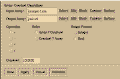 Figure 17.3
Once an input file has been specified, or the output file has been calculated, the
text file may be edited/viewed by pressing the appropriate Edit button. A map of the
file may also be displayed by pressing the Block, Contour, or Surface buttons.
Array-Indicator:
- NOTE: This option is not yet installed!
Array-Reclassification:
Array:Array-Reclassification is used to reclassify a range of values within a grid
to a single new value. The pop-up dialog is shown in Figure 17.4. To use this option
you must specify an Input Array and an Output Array file name. The output file will be
of the same type as the input file. With this option, all values >= Minimum and <=
Maximum will be reset to the Reclassification value. To perform the operation, press the
Calculate button. When the calculation is complete, the operation will be posted in the
log status window (Figure 17.1), and the results will be saved to the specified Output
Array file.
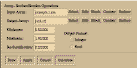 Figure 17.4
Once an input file has been specified, or the output file has been calculated, the
text file may be edited/viewed by pressing the appropriate Edit button. A map of the
file may also be displayed by pressing the Block, Contour, or Surface buttons.
Array-Series:
Array-Array Parameters:
Array:Array-Series:Array-Array Parameters is used to perform basic
mathematical operations on a series of grids. The pop-up dialog is shown in Figure
17.5. To use this option you must specify a Series Prefix and a Series Extension (e.g. for
a series conc.iso.1.srf, conc.iso.2.srf, ..., the prefix would be conc.iso and the extension
would be srf. NOTE "." are placed automatically of either side of the file series number),
the First and Last series number of concern (For best performance, it is best if series
numbers are consecutive), and the Output Array file name. There are five possible
Operations for the grid series: average, sum, minimum, maximum, and probability in
range. For Probability in Range the Minimum and Maximum range values of concern
must also be specified. The Output Format may also be specified as either Integer or
Real. Note: the Integer format will truncate real numbers to the lower integer value (i.e.
4.987 goes to 4). The output file will be of the same type as the input file. To perform
the operation, press the Calculate button. When the calculation is complete, the
operation will be posted in the log status window (Figure 17.1), and the results will be
saved to the specified Output Array file.
 Figure 17.5
Once an input file has been specified, or the output file has been calculated, the
text file may be edited/viewed by pressing the appropriate Edit button. A map of the
file may also be displayed by pressing the Block, Contour, or Surface buttons.
Array-Point Parameters:
Array:Array-Series:Array-Point Parameters is used to determine the value a
series of 2D or 3D grids at an arbitrary X, Y, Z location. The pop-up dialog is shown in
Figure 17.6. To use this option you must specify a Series Prefix and a Series Extension
(e.g. for a series conc.iso.1.srf, conc.iso.2.srf, ..., the prefix would be conc.iso and the
extension would be srf. NOTE "." are placed automatically of either side of the file series
number), the First and Last series number of concern (For best performance, it is best if
series numbers are consecutive), and the Output Array file name.
- NOTE: This option currently does not work on single, non-series files. The program
can be fooled by putting a number in the filename, and setting the First and Last
series number to the same number.
 Figure 17.6
The X, Y, and Z Point Location must also be specified. The output file will be of the same
type as the input file. By default, a new file will be created (an old file, if it exists, will
be overwritten), and the value(s) at the designated location will be printed each time this
option is calculated. It is sometimes convenient to combine the results of several
searches into a single file, and identify the X, Y, and Z coordinates. These options can
be selected by toggling the Append to Existing File and/or Print X, Y, Z buttons. To
perform the operation, press the Calculate button. When the calculation is complete,
the operation will be posted in the log status window (Figure 17.1), and the results will
be saved to the specified Output Array file.
- NOTE: When determining the value at a particular location, different methods are
applied depending on the file type. If the grid is node centered, a point falling
anywhere within the node will be assigned the node value (i.e., there is no
interpolation). If the grid is grid centered, the point of interest will be estimated
using a basis function based on the four surrounding grid points.
Once an input file has been specified, or the output file has been calculated, the
text file may be edited/viewed by pressing the appropriate Edit button. A map of the
file may also be displayed by pressing the Block, Contour, or Surface buttons.
Array-Transform:
- NOTE: This option is not yet installed!
[TOP] [SYNTAX]
Log:
The Log menu option is supplied to allow the user to save, view, or print all text
which has been written to the log/status window by the program or added by the user
(The log window is also a simple text editor). The options include View Log, Save, Save
as, and Print. View Log, Save, and Save as are similar in operation to the menu options
under File described above.
[TOP] [SYNTAX]
Help:
Help lists topics about the program for which there is help. When a item is
selected a pop-up dialog with a scrolled text area is generated which is similar to Figure
5.15 with the desired information.
- NOTE: Only one help window may be open at a time.
Help files are editable ASCII data files; for further information see Appendix D.
[TOP] [SYNTAX]
Example of Using Array:
For an example, a geologic uncertainty map and a contaminant plume map will
be combined to develop a risk or priority map. The resultant map will allow the user to
guide future exploration based on two parameters. The initial maps are products of
sisim and mt3dmain and are based on 100 geologic and contaminant transport flow
simulations. They are:
- geo.iso.cert.srf:
- This map shows the certainty that the modeler knows what
the material type will be a any location within the map area.
conc.iso.mean.srf: - This map shows the mean contaminant concentration for the
flow models. Concentrations vary between 0 and 1000 ppm,
and the EPA drinking water standard is 10 ppm.
conc.iso.std_dev.srf: - This map shows the standard deviation contaminant
concentration for the flow models.
By modifying and combining these maps we can determine several things. By adding
two standard deviations to the mean at each location, the maximum concentration with
a 95% certainty can be calculated. By combining this with the geologic certainty map,
after some manipulation, areas of high geologic uncertainty, and areas near the 10 ppm
EPA standard can be highlighted. This is the zone of most concern for further
investigation because:
- 1). Zones that are shown to be highly contaminated (> 100 ppm), with even further
investigation will probably still exceed the EPA standard. These zones will have
to be remediated, and further investigation here will do little to define the extent
of the plume.
2). Zones that appear uncontaminated, are unlikely to be contaminated, and
require little further exploration. It may be wise to put in observation wells to
insure the plume does not migrate off site, or determine background
contaminant levels, but those are different issues then being described here.
3). Zones with high geologic certainty will yield little further information with
continued exploration, and the results will only minimally change the
contaminant transport flow model predictions.
4). Zones with low geologic certainty, and zones near the EPA standard should be
explored first. Data at these locations will best lower geologic uncertainty and
define the extent of the contaminant plume.
To create these maps, use the following steps:
- 1). Run array.
2). Make the a file representing two contaminant concentration standard deviations.
- Select the Array:Array-Constant menu item.
- Define the Input Array as conc.iso.std_dev.srf.
- Define the Output Array as conc.iso.95.srf.
- Select the * Operation.
- Define the Constant as 2.0.
- Press Calculate.
- Press Done.
3). Make the file representing the maximum likely contaminant concentration with
95% probability.
- Select the Array:Array-Array menu item.
- Define the Input Array 1 as conc.iso.mean.srf.
- Define the Input Array 2 as conc.iso.95.srf.
- Define the Output Array as conc.iso.95max.srf.
- Select the + Operation.
- Press Calculate.
- Press Done.
- This map is shown in Figure 17.7.
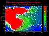 Figure 17.7
4). Make the exploration priority map associated with contaminant concentration.
Risk will be assigned in the following manner:
- 0: 0 ppm, > 100 ppm
- 100: 10 ppm
- Values between 0 and 10, and 10 and 100 ppm will be gradational.
- Reclassify concentrations:
Trim maximum concentration down to 100.0.
- Select the Array:Array-Reclassification menu item.
- Define the Input Array as conc.iso.95max.srf.
- Define the Output Array as junk1.srf.
- Define the Minimum as 100.0.
- Define the Maximum as 1000.0.
- Define the Reclassification as 100.0.
- Press Calculate.
- Press Done.
Values now vary between 0 and 100.
Center EPA 10 ppm level about 0.0.
- Select the Array:Array-Constant menu item.
- Define the Input Array as junk1.srf.
- Define the Output Array as junk2.srf.
- Select the - Operation.
- Define the Constant as 10.0.
- Press Calculate.
- Press Done.
Values now vary between -10 and 90.
Make mask; all values > 0.0 = -10.0 (This will mask out).
- Select the Array:Array-Reclassification menu item.
- Define the Input Array as junk2.srf.
- Define the Output Array as junk3.srf.
- Define the Minimum as 0.0.
- Define the Maximum as 100.0.
- Define the Reclassification as -10.0.
- Press Calculate.
Values now vary between -10 and 0.
Make mask; all values < 0.0 = 100.0 (This will mask out).
- Define the Input Array as junk2.srf.
- Define the Output Array as junk4.srf.
- Define the Minimum as -10.0.
- Define the Maximum as 0.0.
- Define the Reclassification as 100.0.
- Press Calculate.
- Press Done.
Values now vary between 0 and 100.
Shift values from -10 to 0 to 0 to 10, then scale values 0 to 100.
- Select the Array:Array-Constant menu item.
- Define the Input Array as junk3.srf.
- Define the Output Array as junk5.srf.
- Select the + Operation.
- Define the Constant as 10.0.
- Press Calculate.
- Define the Input Array as junk5.srf.
- Define the Output Array as junk6.srf.
- Select the * Operation.
- Define the Constant as 10.0.
- Press Calculate.
- Press Done.
Values now vary between 0 and 100.
Invert values from 0 to 90 to 0 to -90, add 100, then scale values 0 to 100.
- Select the Array:Array-Constant menu item.
- Define the Input Array as junk4.srf.
- Define the Output Array as junk7.srf.
- Select the * Operation.
- Define the Constant as -1.0.
- Press Calculate.
- Define the Input Array as junk7.srf.
- Define the Output Array as junk8.srf.
- Select the + Operation.
- Define the Constant as 90.0.
- Press Calculate.
- Define the Input Array as junk8.srf.
- Define the Output Array as junk9.srf.
- Select the * Operation.
- Define the Constant as 1.1111111.
- Press Calculate.
- Press Done.
Values now vary between 0 and 100.
Add two masked data sets together to create full concentration priority map.
- Select the Array:Array-Array menu item.
- Define the Input Array 1 as junk6.srf.
- Define the Input Array 2 as junk9.srf.
- Define the Output Array as conc.iso.cost.srf.
- Select the + Operation.
- Press Calculate.
- Press Done.
Values now vary between 0 and 100.
This map is shown in Figure 17.8.
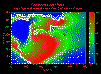 Figure 17.8
5). Make the exploration priority map associated with geologic uncertainty. Risk
will be assigned in the following manner:
- Values between 0.5 and 1.0 will be gradationally scaled, where 1.0 goes to 0
and 0.5 goes to 100.
Reclassify geologic uncertainty:
Make 1.0 --> 0.0.
- Select the Array:Array-Constant menu item.
- Define the Input Array as geo.iso.cert.srf.
- Define the Output Array as junk1.srf.
- Select the - Operation.
- Define the Constant as 1.0.
- Press Calculate.
Values now vary between -0.5 and 0.0.
Flip values: -0.5 --> 0.5.
- Define the Input Array as junk1.srf.
- Define the Output Array as junk2.srf.
- Select the * Operation.
- Define the Constant as -1.0.
- Press Calculate.
Values now vary between 0.0 and 0.5.
Scale values between 0 and 100.
- Define the Input Array as junk1.srf.
- Define the Output Array as geo.iso.cost.srf.
- Select the * Operation.
- Define the Constant as 200.0.
- Press Calculate.
- Press Done.
Values now vary between 0 and 100.
This map is shown in Figure 17.9.
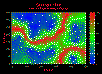 Figure 17.9
6). Merge two exploration priority maps into a single priority map. Note, the highest
priority will be 10000 (100 x 100), an the lowest will be 0 (0 x 0).
- Multiply costs by one another.
- Select the Array:Array-Array menu item.
- Define the Input Array 1 as conc.iso.cost.srf.
- Define the Input Array 2 as geo.iso.cost.srf.
- Define the Output Array as priority.iso.srf.
- Select the * Operation.
- Press Calculate.
- Press Done.
Values now vary between 0 and 10000.
This map is shown in Figure 17.10.
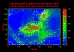 Figure 17.10
In this example both maps are scaled equally. If one map was felt more important, it
could be scaled (x) first by the appropriate weight, before the two maps were multiplied
together.
[TOP]
Running From the Command Line:
In many cases it is more convenient to run the application completely from the
command line, or at least pass some parameter values in from the command line. The
options listed below allow the user to accomplish almost anything that is possible from
within the X-windows application from the command line. This feature can be useful
when the user does not have a X-windows/Motif terminal available, or when many
graphs need to be processed quickly, and the operation can be completed in batch
mode without user interaction.
Syntax:
- array
[-af #]
[-aor #]
[-cor #]
[-cst #.#]
[-df " "]
[-fmt #]
[-help]
[-lgf " "]
[-pmn #.#]
[-pmx #.#]
[-ota #]
[-otc #]
[-ots #]
[-prf " "]
[-pxyz #]
[-rmn#.#]
[-rmx #.#]
[-runa]
[-runc]
[-runp]
[-runr]
[-runs]
[-runv]
[-s1f " "]
[-s2f " "]
[-sed #]
[-sef " "]
[-ssf " "]
[-sst #]
[-xpt #.#]
[-ypt #.#]
[-zpt #.#]
- Meaning of flag symbols:
- # = integer
#.# = float
" " = character string.
{} = variable is an array. Values must be seperated by a ',' and no spaces
are allowed. Do not use the "{ }" symbols on the command line.
NOTES:
- 1). All parameters in [] brackets are optional.
2). Quotes must be used around character strings.
Flag Definitions:
-
| -af | = |
append file | default = 0 |
| |
|
| -aor | = |
array operation order | default = 0 |
| |
0
1 |
=
= |
Array 1 ? Array 2
Array 2 ? Array 1 |
|
| -cor | = |
constant/array operation order | default = 0 |
| |
0
1 |
=
= |
Array ? Constant
Constant ? Array |
|
| -cst | = |
constant value | default = 1.0 |
| -df | = |
destination file name | default = " " |
| -fmt | = |
output file format | default = 1 |
| |
0
1 |
=
= |
integer
floating point |
|
| -help | = |
give this help menu | |
| -lgf | = |
log file name | defalut = "log.dat" |
| -ota | = |
array operation type | default = 0 |
| |
0
1
2
3
4
5
6 |
=
=
=
=
=
=
= |
add
subtract
divide
multiply
average
maximum probability
minimum probability |
|
| -otc | = |
constant/array operation type | default = 0 |
| |
0
1
2
3 |
=
=
=
= |
add
subtract
divide
multiply |
|
| -ots | = |
series operation type | default = 0 |
| |
0
4
5
6
7 |
=
=
=
=
= |
sum
average
maximum probability
minimum probability
probability in range |
|
| -pmn | = |
minimum probability | default = 0.0 |
| -pmx | = |
maximum probability | default = 1.0 |
| -prf | = |
preference file name | defalut = "array.prf" |
| -pxyz | = |
print X, Y, Z coordinates | default = 0 |
| |
|
| -rcl | = |
new reclassification value | default = 0 |
| -rmn | = |
minimum range | default = 0.0 |
| -rmx | = |
maximum range | default = 0.0 |
| -runa | = |
run array-array | |
| -runc | = |
run array-constant | |
| -runp | = |
run series array-point | |
| -runr | = |
run array-reclassify | |
| -runs | = |
run series array-array | |
| -runv | = |
run MODFLOW VCONT | |
| -s1f | = |
source #1 file name | default = " " |
| -s2f | = |
source #2 file name | default = " " |
| -sed | = |
ending series number | default = 1 |
| -sef | = |
source series file name extension | default = " " |
| -ssf | = |
source series file name prefix | default = " " |
| -sst | = |
starting series number | default = 1 |
| -xpt | = |
X search location | default = 0.0 |
| -ypt | = |
Y search location | default = 0.0 |
| -zpt | = |
Z search location | default = 0.0 |
An example command might be (typed on one line):
- array -cst 5.0 -s1f conc3.srf -df junk.srf -otc 3
[TOP]
Input & Output Files:
Array determines automatically what the input file format is when a grid is read.
Note, that the format must be one of the standard grid formats defined in the contour,
surface, or block (Chapters 11,
12, & 13) chapters.
The output file format will be the
same as the import file format unless otherwise specified (Some SISIM3D results will be
converted to block formats). 2D files are formatted as specified for the programs contour
and surface (Chapters 11 &
12). 3D files are formatted for the program block
(Chapter
13). See the relevant chapters for a description of the data file formats.
[TOP]
Array Mathematics:
The mathematics used in array are fundamentally the same as those described
in histo (Chapter 6).
[TOP]
Table of Contents
Previous Chapter
Beginning of this Chapter
Next Chapter